Raking Systems for Waste Paper Pulpers
Aggregates and individual components for Waste Paper Pulpers
Application
The suspension that rotates in the pulping process in the waste paper pulper spins the contrary material that came in with the waste paper, such as, e.g. wires, films, plastic and insoluble paper, into a rope.
If only smaller disconnected ropes are formed, so that raking using a rope winch is very complicated, we recommend using Lohse raking systems, which can be adapted to the respective operations (periodic or continuous).
Construction
Typ R (rake)
Suitable for extracting contrary material that does not twist into a rope during the pulping process.
Typ H (hook)
Suitable for extracting contrary material that twists into short rope lengths during the pulping process.
Typ K (combination)
Suitable for extracting short rope lengths and short, non-roping contrary material.
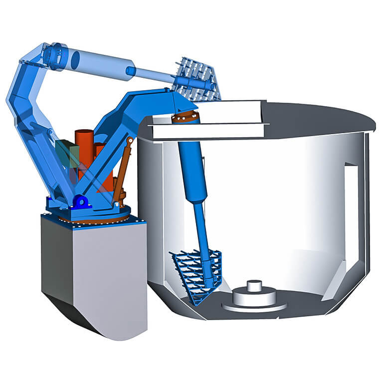
Installation and function
The stand-alone appliance is fastened to the floor next to the waste paper pulper. A discharge station (chute or funnel) into a transport container must be installed in the swivelling radius of the collecting arm, which runs contrary to the direction of the waste paper pulper. When at a standstill the swung out collecting arm stops above the discharge station.
A cleaning cycle is initiated when the waste paper pulper is pumped off and the residual suspension in the tank has been diluted back down to a material density of 1.5% to 3% with the required process water for the next pulping process.
A hydraulic rotary actuator swings the collecting device from its starting position into the collecting position above the waste paper pulper. Two hydraulic lifting cylinders lowers the collecting arm into the waste paper pulper in its collecting position, where it remains for a period determined in experiments. On expiry of this dwell time the collecting arm is lifted out of the waste paper pulper and stops above the waste paper pulper for a defined draining period. The loaded collecting device then swings out over the edge of the waste paper pulper to the discharge station. Here a hydraulic rotary actuator turns the collecting arm so that the rejects fall out of the teeth.
The collecting process can be repeated several times, depending on the contrary material. The control sequence can be carried out at an integrated electric switchgear cabinet in manual or in automatic mode.
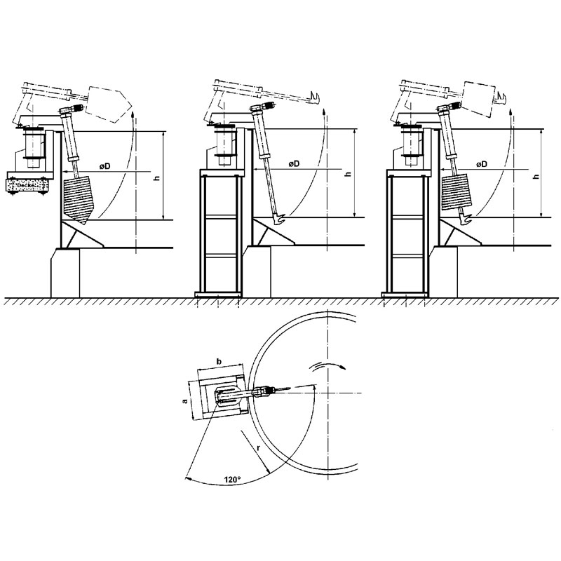
Technical drawing
Technical data
| Size | 1 | 2 | 3 | |
| dip in depth / waste paper pulper | h / mm | <= 2700 | <= 3300 | <= 3300 |
| swinging distance | r / mm | 2700 … 3000 | ||
| swinging angle | angle | 120 | ||
| operation * | periodic | |||
| interval time * | adjustable by timer | |||
| diving time pulper | min. | 0,5 … 1 | ||
| total operation time | min. | 4 | ||
| reject weight aprox. ** | ||||
| type R (rake) | ~ kg | 20 … 30 | 30 … 40 | 40 … 50 |
| type H (hook) | ~ kg | 20 | 30 | 40 |
| type K (combination) | 25 | 35 | 45 | |
| hook drive | kW | 1,5 | 2,2 | 3 |
| swinging drive | kW | 2,2 | 3 | 4 |
| hydraulic drive | kW | 7,5 | 11 | 15 |
| height drive *** | mm | max. height 1800 above pulper top | ||
| basic dimensions | a x b mm | 1100 x 1500 | ||
| place of installation | beside pulper | |||
* depending of reject volume and pulpersize
** balanced on waste paper mix B12 / B19
***rakearm in top position befor swinging